Amplitude Modulation
What is modulation?
Modulation is the process of modifying a carrier signal such that it is able to propagate in the channel we intend to send it through and also that it contains the “information” signal we want to communicate
what is amplitude modulation?
the process of manipulating/modifying the amplitude of the carrier signal \(f_{c}\)
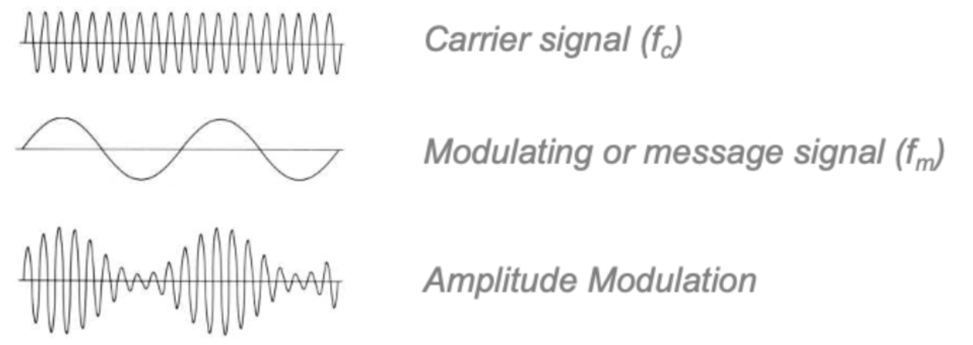
what is carrier signal?
A carrier singal is type of waveform (mostly a pure $\sin$ wave) that is used to transmit the information, it itself not does contain the information thus it serves as medium that modified(modulated) in some to way to encode the message
A carrier can be expressed in the from \(v(t)=A\sin(\omega t +\phi)\)
varying \((\omega t +\phi)\) cause the angle modulation of the carrier, there are two forms of angle modulation:
- Phase modulation $\phi$ which changes the phase
- Frequncuy modulation $\omega$ which changes the frequency
Modulation Depth (m)
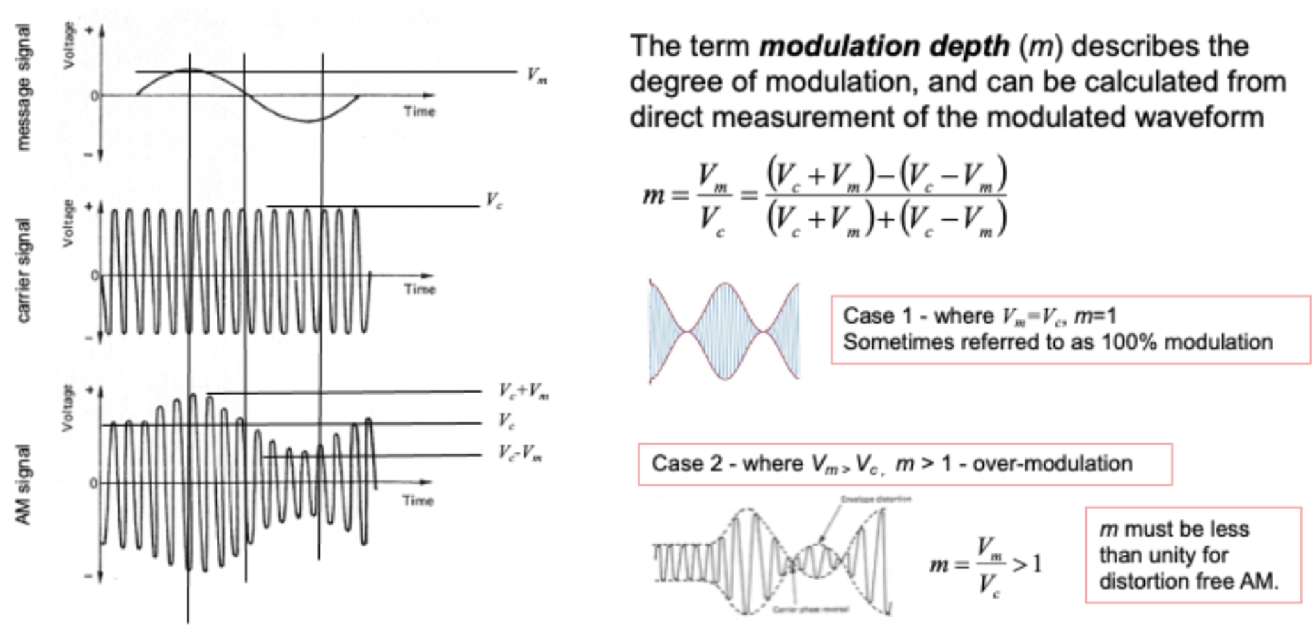
Moddulation depth :- describes the degree of modualtion and can be calcualted from a direct measurment of the modualted waveform
\[m=\frac{V_m}{V_c}=\frac{(V_c + V_m)-(V_c - V_m)}{(V_c + V_m)+(V_c - V_m)}\]-
Modulation Depth = 0: This is a scenario where the modulating signal has zero amplitude, meaning there is effectively no modulation occurring. The output signal will simply be the carrier wave with no variations representing the information signal.
-
Modulation Depth = 1 (100%): This is considered full modulation, where the amplitude of the modulating signal is equal to the amplitude of the carrier wave. At maximum modulation, the carrier amplitude can be reduced to zero during the modulation cycle, but it should not invert (i.e., go negative), which would lead to distortion known as overmodulation.
-
Overmodulation (>100%): If the modulation depth exceeds 1, the carrier wave’s amplitude is forced beyond zero into negative amplitudes during parts of the modulation cycle, causing signal distortion and creating additional unwanted frequencies in the spectrum.
Amplitude Modualtion in Frequency Domain
$A = V_c + V_m\sin(\omega_m t)$
$\therefore v(t)={V_c + V_m\sin(\omega_m t)}\cdot {\sin(\omega_c t)}$
Get modualation index so divide by $V_c$
$v(t)={1 + m\sin(\omega_m t)}\cdot V_c\cdot {\sin(\omega_c t)}$
$V_c \sin(\omega_c t) + [mm\sin(\omega_m t)\cdot V_c\sin(\omega_c t)]$
$V_c \sin(\omega_c t) + mV_c[\sin(\omega_m t)\cdot \sin(\omega_c t)]$
\[\therefore v(t)= V_c \sin(\omega_c t) + \frac{mV_c}{2}[\cos(\omega_c t-\omega_m t)-\cos(\omega_c t +\omega_m t)]\]Use tring identity to simplify $\sin(A)\sin(B)=\frac{1}{2}[\cos(A-B)-\cos(A+B)]$ Basics of mixing
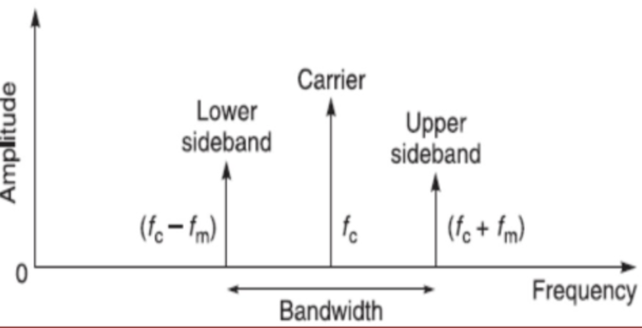
Carrier Breakdown
Signal Carrier $= V_c \sin(\omega_c t)$
Lower Sideband Carrier $= \cos(\omega_c t-\omega_m t)$
Upper Sideband Carrier $= \cos(\omega_c t+\omega_m t)$
The sideband amplitudes are generally less than the carrier, at least in DBS-AM, and where the modulation index is less than unity
Adding more modulation tones
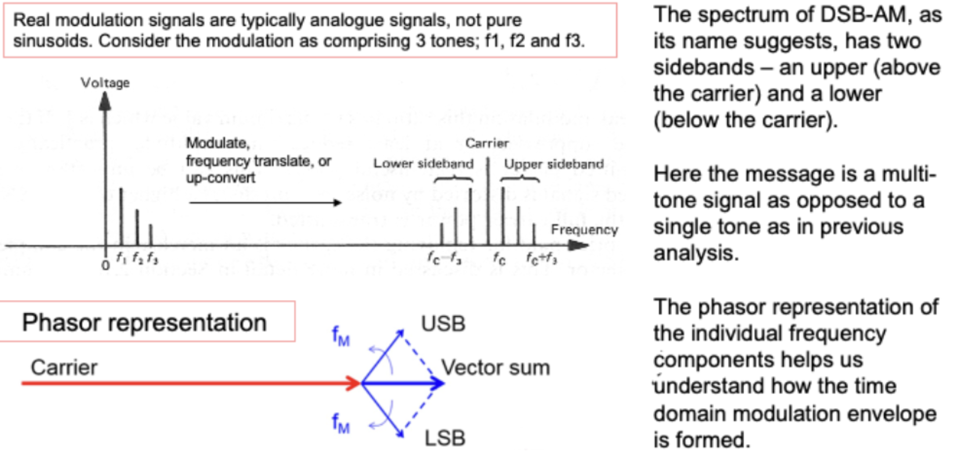
- Three Frequency Components: Let’s assume the modulating signal has three distinct frequencies: $F_1$, $F_2$, and $F_3$. These could be different tones in an audio signal, for example.
- Non-Sinusoidal Nature: When you combine these three different frequencies together, the resulting modulating signal isn’t a simple sine wave anymore; it becomes a more complex, non-sinusoidal waveform. This means it has a shape that’s not just a single, repeating curve but a more intricate pattern formed by the interaction of the three frequencies.
- Using a Mixer: A mixer or multiplier is used to combine the modulating signal with the carrier. This process is known as upconversion because it shifts the frequencies of the modulating signal from their original lower range (near DC) to a band centered around the high frequency of the carrier.
Generation of sidebands
-
When the modulating signal (with components $F_1$, $F_2$, and $F_3$) is mixed with the carrier frequency ($F_c$), new frequencies are created around the carrier frequency. These new frequencies are called sidebands (upper and lower).
-
Multiple Sidebands: Since the modulating signal consists of three different frequencies, this process results in multiple sidebands for each. Specifically, you would see six key sidebands: two for each frequency component ($F_1$,$F_2$,$F_3$).
Resulting Frequency Spectrum
- Broad and continuous range of sidebands around the carrier.
- Spectrum is symmetric around the carrier frequency, showing a mirrored distribution of frequencies in USB and LSB.
Importantly, each of these two bands, either side of the carrier, contain all of the information signal, so its duplicated.
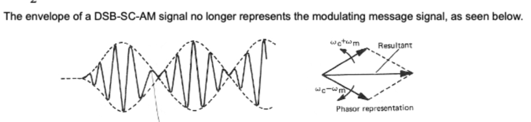
Phasor Diagram
If we consider again our simple 3 frequency modulated signal, we can then imagine the modulation USB and LSB tones asphasors rotating around the end point of the carrier phasor, in a symmetrical fashion, one rotating clockwise and theanticlockwise.Due to the symmetrical rotation of these two phasors, the resultant vector sum only ever varies in magnitude, and never phase.This clearly describes the amplitude modulation we see in the modulated time domain waveform – there is clearly no phase.
Power in DSB-AM
The total power developed in a load assuming $1\Omega$ resistance and peak voltage is
$P_{total}=P_{carrier}+2P_{sideband} = (\frac{V_c}{\sqrt{2}})^2 +2(\frac{ mV_c}{2\sqrt{2}})^2$
$=(\frac{V^2_c}{2}+\frac{m^2 V^2_c}{4})=\frac{V^2_c}{2}\cdot(1+\frac{m^2}{2})$
$(\frac{V_c}{\sqrt{2}})^2\cdot(1+\frac{m^2}{2})=P_{carrier} \cdot (1+\frac{m^2}{2})$
We can see that the total power will be 1.5 times the carrier power & on $\frac{1}{3}$ is usefull as the information is only in one sideband $\therefore \frac{2}{3}$ of the power is wasted
Double Sideband - Suppressed Carrier (DSB-SC-AM)
The DSB-SC-AM is a type of amplitude modulation where the carrier ($f_c$) is suppressed and onlt the sidebands are transmitted as they are also radio frequencies.
Due to this more power saving can be made as the carrier signal does not carry any information and it is east to make all we need to do is multiply the message signal with the carrier signal with no DC offset.
The only issue is that the signal cannot be extracted as easily using a simple diode circuit as it is “overmodulated” thus a more complicated needs to be taken which requires the presense of the carrier signal.
One technique is to recreate the carrier however at the point of reception, or transmit a much smaller, pilot tone thatcan be amplified by the receiver and used in the demodulation process
$v(t)=A_c \cos(\omega_c t) \cdot A_m\cos(\omega_m t) = \frac{A_c A_m}{2}{(\cos(\omega_c t + \omega_m t)+ \cos(\omega_c t - \omega_m t)}$
Single Sideband - Suppressed Carrier (SSB-SC-AM)
As in a DSB-SC-AM the carrier is suppressed but both the sidebands are transmitting duplicated data their still lack efficency as we are effectively transmitting the same information twice
We could therefore suppress the carrier and one the sideband either the lower or upper one to get SSB-SC-AM
We can make a SSB-SC-AM by first creating a DSB-SC-AM signal and them filtering out one of the side band (lower or upper)
We can still recover information at receiver but added compolexity is don as we need to create the original carrier signal (in most cases worth it)
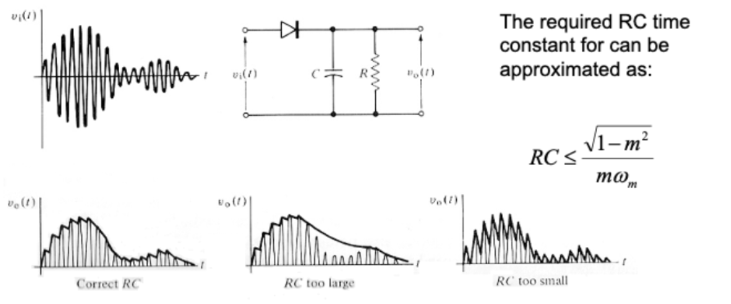
DSB-AM Demodulation (simple, non cohernet)
A simple DSB-AM detector can comprise a forward bias diode as a half eave wave rectifer, together with a capacitor and a load resistor.
We apply the modulated carrier to the diode to rectify it leaving only the positive going parts of each RF cycle to charge the capacitor.
As each half cycle $\pi$ the carrier returns to, the charged capactior discharges into the load represented by $R$
The rate of this discharge depends upon the size of the capacitor and the load of course, so it needs to be just right
RC Values (Edge Cases)
If the capacitor discharges too quickly, or if the RC constant is too small, the demodulated signal becomes too noisy, too slowly, and the detector is unable to respond quickly enough track the envelope.
Not quickly enough, and the detector isn’t able to respond to the message signal, and the information itself is effectively filtered out
The required RC time constant can be approximated as $RC \leq \frac{\sqrt{1-m^2}}{m\omega_m}$
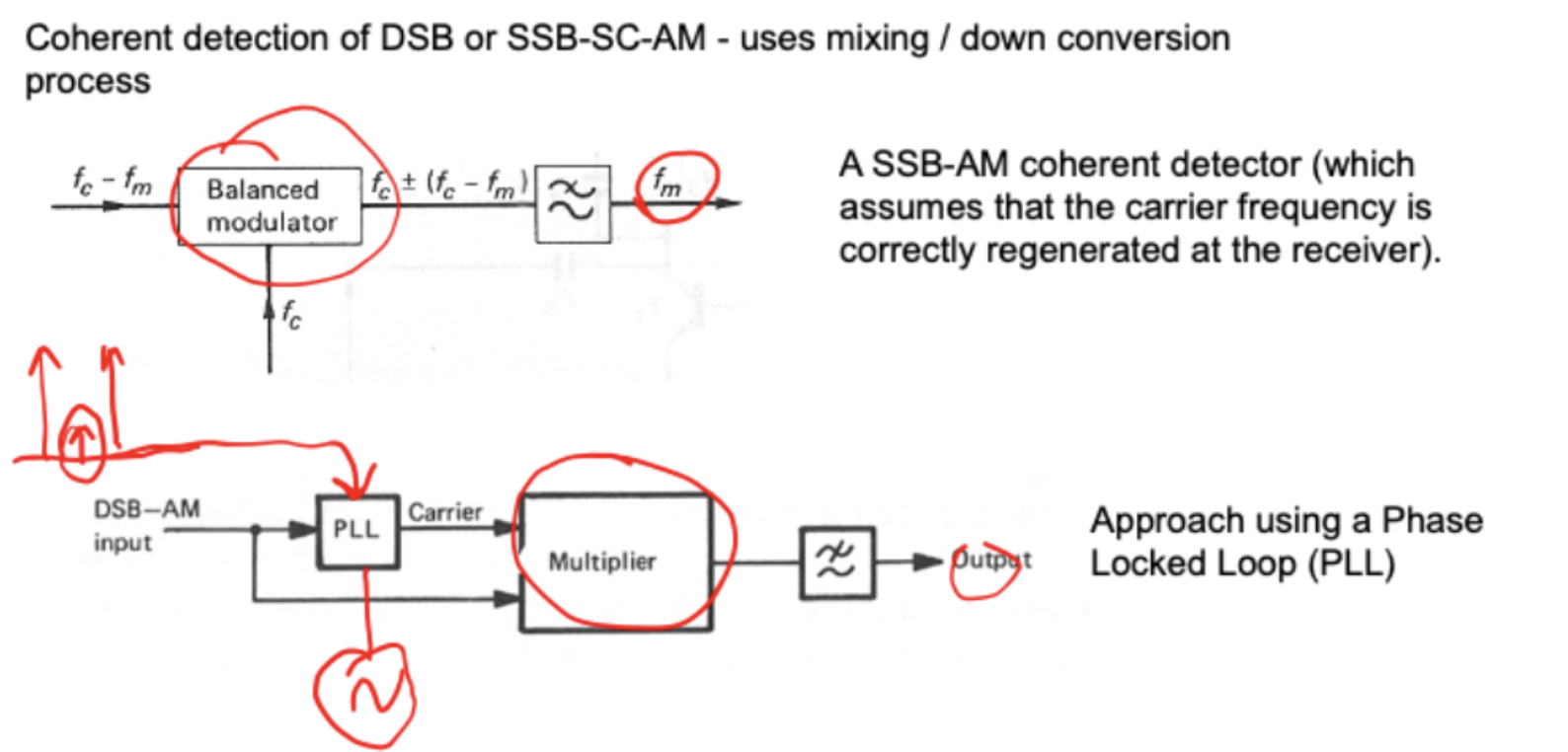
AM Demodulation (Cohernet)
We feed our input, which has been filtered such that only the $F_c-F_m$ components are present, to a ‘balanced’ modulator or mixer,We then take a locally synthesized carrier, $F_c$, and apply this to the other input of the mixer.
Through mixer action, and generation of sum and difference frequencies, the output of the mixer will containmixing products, crucially including $F_c \pm(F_c - F_m)$, which is the message signal we need.
Any small differences between Fc at the transmitter and Fc local, willresult in a change in the demodulated $F_m$, and distortion.
one way around this is to use something called a phase locked loop
This is a similar circuit, but where a phased lock loop (PLL) is used to phase-lock a local oscillator onto a small pilot tone that is received along with the signal, and it uses this regenerate an identical, local coherent carrier thatcan then be used in the demodulation process.
Power in FM/PM
The total power in FM/PM is independant of the modulation index, $\beta$
Calculating the total power as the squared RMS voltage divided by the load resistance, R:
$P_R=\frac{(V_C/\sqrt{2})^2}{R}=\frac{V_c^2}{2R}$