Angle Modulation
Recap
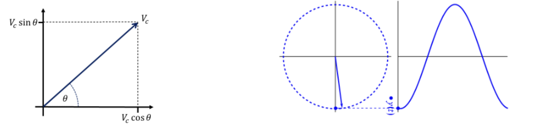
We can represent signals as sine or cosine wave with an amplitude,frequency and phase offset
$v_c(t)=V_c cos(2\pi f_ct +\phi) = V_c cos(\omega_c t +\phi)$
The more general way of writing is to combine the terms for cosine :- amplitude,frequency and phase offset, $v_c(t)=V_c cos(\theta(t))$ this also give us the phasor representation
In Amplitude Modulation we encoded our information signal onto the carrier signals amplitude, $V_c$
Phase, $\theta$ controls the value of the sinusoid. Instantaneous phase, $\theta(t)$ is the phase angle of asignal at any given instant.
Frequency, $f$ is the rate of change of the phase instantaneous frequency, $f(t)$ is the frequency of asignal at any given instant.
The equation $\frac{d}{dt}θ(t)=2πf(t)$ is a mathematical way of describing how the phase of a wave changes over time
General Equations for Frequency and Phase Modulated Signals
For both, the general steps are the same; we’re just finding an expression for $\theta(t)$ and substituting into our general signal form: $v_c(t)=V_c cos(\theta(t))$
We will always know either $f(t)$ or $\theta(t)$, for angle modulation one of these will be dependant on our message signal, $v_m(t)$
If $\theta(t)$ is already known we can just substitute it in, if not we find it from $f(t)$ by integration using the relationship between them: $\frac{d}{dt}θ(t)=2πf(t)$
An unmodulated carrier signal is just going to be a sinusoid with constant frequency: $f(t)=f_c$
As we know $f(t)$, we can find $\theta(t) buy integrating the formula earlier $\frac{d}{dt}θ(t)=2πf(t)$
\[\theta(t) = 2\pi \int_{0}^{t} f_c dt = 2\pi f_c t + \phi\]Substituting into our general signal equation gives us the familiar result: $v_c(t)=V_c cos(2\pi f_ct +\phi) = V_c cos(\omega_c t +\phi)$
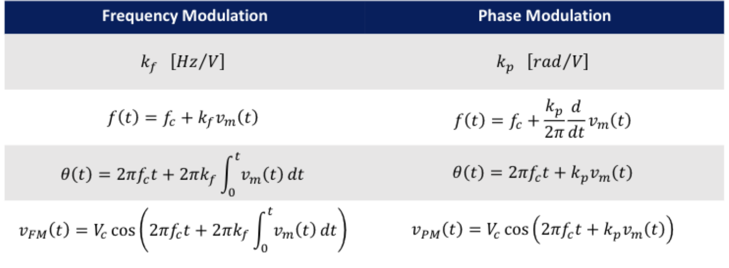
For Phase Modulation we modulate the instantaneous phase according to the message signal:
\[\theta(t)=2\pi f_c t +k_p v_m (t)\]where $v_m (t)$ is our message or information signal $k_p$ is our phase sensitivity factor in $rad/V$ and $f_c$ is the unmodulated carrier frequency
As we have $$\theta(t) we can define our phase modulation singal equation:
\[v_{PM}=V_c \cos(2\pi f_c t +k_p v_m (t))\]we can also define instantaneous frequency
$f(t)=\frac{1}{2\pi} \frac{d\theta (t)}{dt}= f_c + \frac{k_p}{2\pi} \frac{d}{dt}v_m(t)$
- The advantage of this is that the same modulating circuits can be used for both.
- The disadvantage is that the two are indistinguishable from each other before demodulation.
Modulation Index
The values in front of the sine term will determine how much the carrier signal is modulated by the message. we define modulation index, $\beta$.
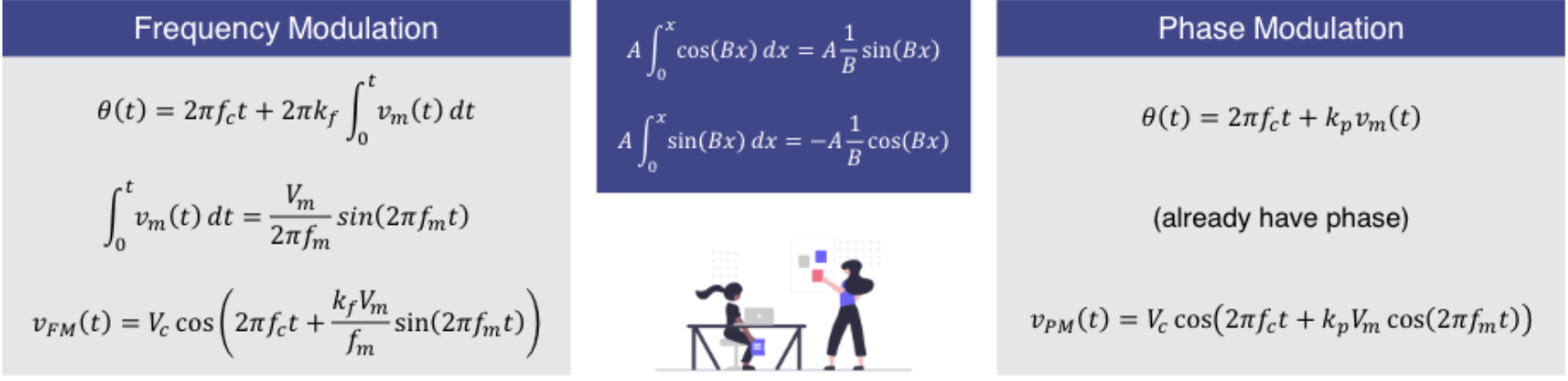
| Frequency Modulation | Phase Modulation |
| \(v_{FM}(t)= V_c \cos(2\pi f_c t + \frac{k_f V_m}{f_m}\sin(2 \pi f_m t))\) | \(v_{PM}(t)= V_c \cos(2\pi f_c t + k_p V_m \cos(2\pi f_m t))\) |
| \(v_{FM}(t)= V_c \cos(2\pi f_c t + \beta_p \sin(2 \pi f_m t))\) | \(v_{PM}(t)= V_c \cos(2\pi f_c t + \beta_p \cos(2\pi f_m t))\) |
| \(\therefore \beta_f= \frac{k_f V_m}{f_m}\) | \(\therefore \beta_p= k_p \cdot V_m\) |
| :Unit Table: | |
| FM | PM |
| $k_f$ - sensitivty factor $[Hz/V]$ | $k_p$ - sensitivty factor $[Hz/V]$ |
| $V_m$ - message amplitude $[V]$ | |
| $f_m$ - message frequency $[Hz]$ | |
| $\beta_f$ - modulation index $[1]$ | $\beta_p$ - modulation index $[rad]$ |
Deviation Ratio
The maximum frequency deviation $f_d$ for any angle modualtion scheme is said to be the largest possible deviation in the frequency from the carrier frequency $f_c$ expressed as:
\[f(t)=f_c + k_f v_m(t)\]We can see that in FM maximum deviation will occur when $v_m$ is maximum if the message is sinusodial this is simply given by the ampltiude $\therefore f_d = k_f V_m$.
In a more complex system that send audio,video etc it will contain more sinewaves with different frequencies, a deviation ratio can be defined as the ratio between $f_d$ and the maximum possible message frequency
\[D= \frac{f_d}{f_{d,MAX}}\]Modulation Index = Deviation ratio when $f_m = f_{m,MAX}$
Bandwith
The amount of spectrum required to transmit the signal
For a real life, multi-tonal FM (or PM) signal it is functionally impossible to derive an expression for bandwidth.
But if we use a single-tone signal for the message then derivation is possible. Starting with out FM signal equation:
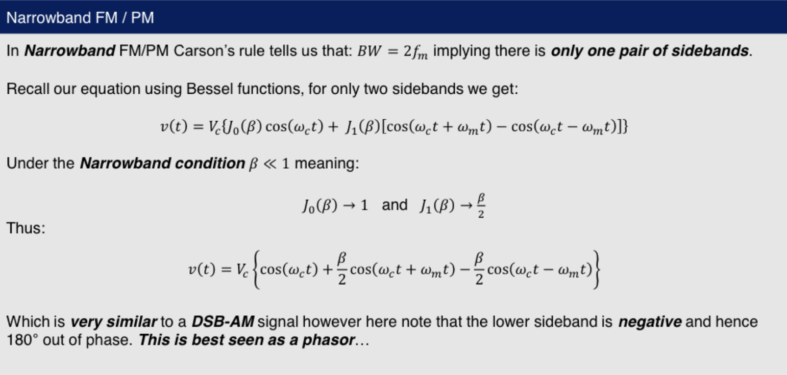
$v_{FM}(t)=V_c \cos(\omega_c t + \beta \sin[\omega_m t])$
We expand this by applying the angle-sum trig identity:
\[v(t)=V_c{cos(\omega_c t)\cos(\beta \sin[\omega_m t]) - \sin(\omega_c t)\sin(\beta \sin[\omega_m t])}\]With the equation in this form we can use the Jacobi-Angerexpansion to give us an expression where the individual sideband frequencies are grouped together using Bessel functions.
Badwith from Bessel Functions
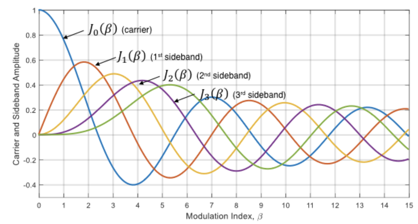
$J_n(\beta) are Bessel functions of the first kind with order $n$ and argument $\beta$, the FM signal equation can be defined as
\[v(t) = V_c {J_0(\beta)\cos(\omega_c t)}\\ + J_1(\beta){\cos(\omega_c t + \omega_m t) -\cos(\omega_c t - \omega_m t)} \\ + J_2(\beta){\cos(\omega_c t + 2\omega_m t) -\cos(\omega_c t - 2\omega_m t)} \\ + ...\]Due to this we see that signal that are composed with multiple tones at different frequencies
- One at the carrier frequency $f_c$ with ampltiude $J_0(\beta)$
- A number of sidebands at ($\omega_c \pm i\omega_m$) with amplitudes $J_i(\beta)$ for values of $i=1,2,3,… \infty$
When defining bandwidth for FM (or PM) we only consider sidebands whose amplitude is $\geq 1%$ of the carrier signal amplitude ($V_c$). So despite there being an apparent infinite number of sidebands, we only need considerthe first few.
For sidebands evenly spaced by the message frequency $BW = J_n(\beta) \times 2 \times f_m$
Carson’s Rule
Another way to determine bandwith is to use Carson’s rule:
| :Edge Cases: | ||
| :Wideband: | :($\beta \gg 1$): | :$BW=2f_m(1+ \beta)$: |
| :Narrowband: | :($\beta \ll 1$): | :$BW=2f_m(1+ \beta) \approx 2f_m$: |
Carson’s rule is less effective between these limits
To improve accuracy for multi-tone signals the rule should be applied using the highest or lowest value of $\beta$ depending on whether it is wideband or narrowband:
- Wideband: $BW=2 \cdot min(f_m)(1+\beta)$
- Narrowband: $BW=2 \cdot max(f_m)(1+D)$
As $\beta \propto Τ_1$ 𝑓𝑚 bandwidth does not change with message frequency.
In phasor diagram the modulated singal $f_m$ is out of phase with the carrier signal $f_c$ as we are varying the phase unlike amplitude modulation where the phase remains the same.
Power in FM/PM
The total power in FM/PM is independant of the modulation index, $\beta$
Calculating the total power as the squared RMS voltage divided by the load resistance, R:
$P_T=\frac{(V_C/\sqrt{2})^2}{R}=\frac{V_c^2}{2R}$
\[P_T = P_c\]Shows that $P_T$ is totally dependent on the original carrier signal power:
If a specific sideband or carrier power needs to be calculated it can be done by the incorporation of the bessel function into the previous _power equation__
$P_T=\frac{(V_C J_n(\beta)/\sqrt{2})^2}{R}=\frac{(V_c J_n(\beta))^2}{2R}$
$\therefore$ the total sum of the carrier and sidebands is
\[P_T = P_{carrier} + P_{sidebands}= \frac{(V_c J_0(\beta))^2}{2R} + \sum_{n=1}^{\infty}[\frac{(V_c J_n(\beta))^2}{R}]\]Bessel function gradually dampen when $\beta$ is increased $\therefore$ increasing the modulation index distrubutes more power amongst the sidebands while reducing the power of carrier
Power Efficiency
As in FM the information from the message singal is contained by the sidebands and not the carrier power efficiency ,$\eta$, can be calcualted by the percentage of the total power contained in the sidebands.
\[\eta=\frac{P_{sidebands}}{P_{total}}\]Increaseing $\eta$ will increase with $\beta$ (vice versa)
As there are infinite sidebands it would require a calcualation going to infinity
Due to the fact total power $P_{total}$ is independent of modualtion index $\beta$, $\therefore$ the toatal power in the sideband the total amount of power not in the carrier frequency $f_c$
\[\eta=\frac{P_{sidebands}}{P_{total}}=\frac{P_{total}- P_{carrier}}{P_{total}}=1- \frac{P_{carrier}}{P_{total}}\]Another way of using the equation with equation defined earlier
\[\eta=\frac{P_{c}}{P_{T}}=1-\frac{2R V_c^2 J_0(\beta)^2}{2R V_c^2}\]Simplified
\[\eta=1-J_0 (\beta)^2\]Direct and Indirect Modulation
| The type of modulator used (direct | indirect) determines weather it will produce FM or PM |
A direct FM modualtor is an indirect PM modulator (vice versa).
This modification can be made before hand by eithere Integrating or differenitating the message signal before hand
VCO Synthesis
In Direct VCO Synthesis the message signal is used to drive a voltage controlled oscillator (VCO) which produces an FM signal.
A VCO is a type of signal generator where output frequency is determined by the input voltage:
$f_{vco}(t)=f_0 + K_0 \cdot v_in(t)$
Where $f_0$ is the centre frequency of the VCO and $K_0$ is the sensitivity of the VCO
if $v_m$ is fed directly into the vco the output frequency is instantaneous frequency of the FM signal
\[k_f=K_0 \\ f_c =f_0\]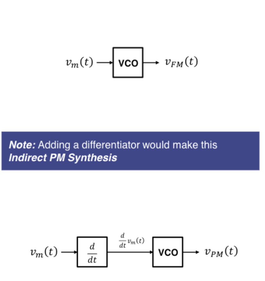
Normally the VCO frequency will not be exactly thesame as our desired carrier frequency, so a small DC voltage is added
\[v_in(t)=v_m(t) +V_{DC}\] \[\therefore f_{vco}(t)=f_0 + K_0[v_m(t) +V_{DC}]\]Rearranging gives us our new adjustable carrier frequency $f_{vco}(t)=f_0 + K_0 v_m(t)$ $f_c = f_0 +K_0 V_{DC}$
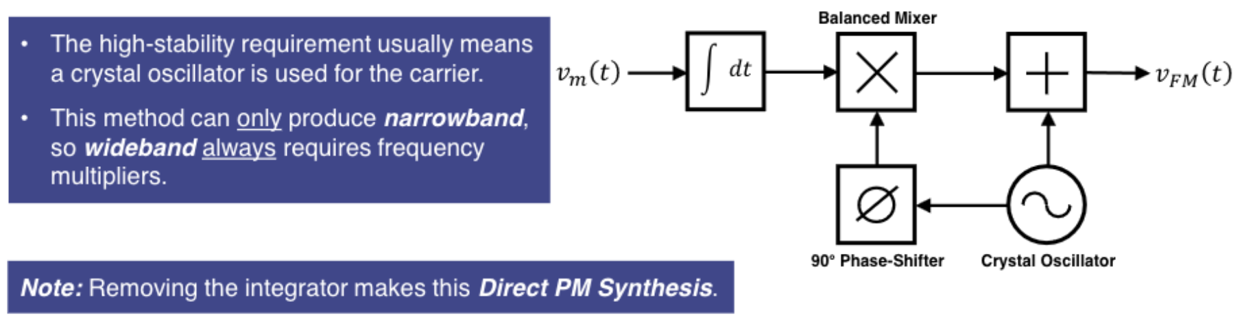
Armostrong Synthesis (Product Modulation)
Armstrong synthesis is an indirect FM modulation method and so the message signal must be integrated.
A highly-stable signal source is used to produce the carrier signal which is phase-shifted 90° before being product modulated by the message signal. The original carrier signal is then added to the output of the mixer, producing a very stable narrowband FM signal.
Demodulation
An FM demodulator can be used as a PM demodulator by integrating the output signal.
A PM demodulator can be used as an FM demodulator by differentiating the output signal.
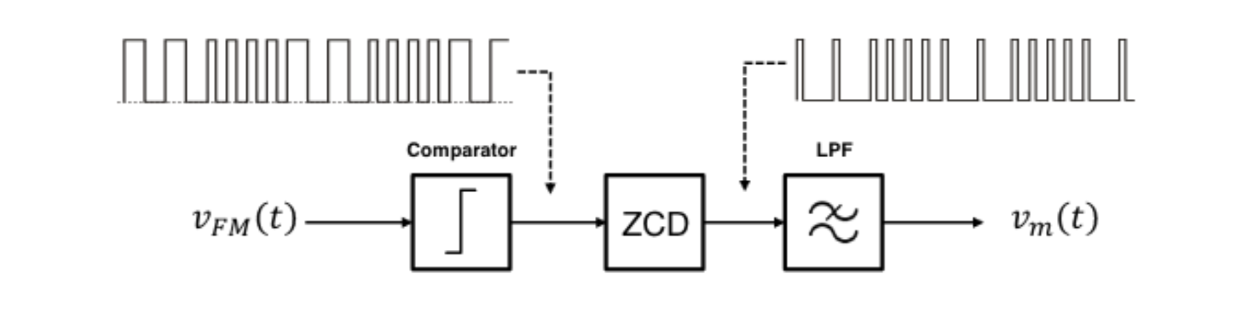
Zero Cross Detection
- Consists of three primary components
| :Component: | :Definition: |
| Comparator | Coverts the recieived signal to a square wav, comparator work by thresholding the input signal; setting the output high or low based on the setting |
| Zero Cross Detector | Output a fixed length pulse whever it detects a rise of falling edge on the input,Since the pulse length is fixed, the spacing between pulses will be dependant on the instantaneous frequency of the original FM (or PM) signal |
| Low Pass filter | The spacing between pulses give rise to a changing DC voltage equal to the message signal,Passing this through a low-pass filter isolates this component, allowing the message signal to berecovered |

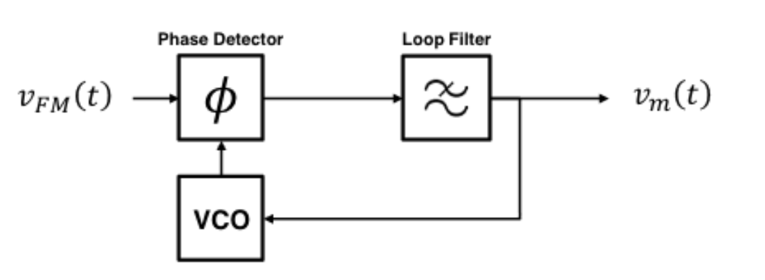
Phase Detection
A PLL is a type of synthesiser where the output stability from a VCO is improved by comparing it to a reference signal from a crystal oscillator. A phase detector generates an error voltage proportional to the phase difference between the two signals.
When used for FM demodulation; we use the received FM signal as the reference and so the error voltage generated is actually the demodulated signal. This is fed into the VCO causing it to constantly change frequency to match the received signal.
A loop filter is used to remove any high frequency noise which could lead to instability in the feedback loop